Flex PCBs for Roll-To-Roll Manufacturing
Flex PCBs for Roll-To-Roll
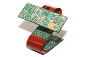
The PCB (printed circuit board) is a laminated structure of conductive insulated layers that host and connect electronic components. It is a key component in most electrical products and devices. The PCB connects the component terminals and conductive pads via copper traces, planes, and other features. It also serves to shield these components from electromagnetic interference, as well as provide a means of thermal dissipation. The PCB must be designed to accommodate these functions and the desired bending and foldability of the final product.
There are a variety of different types of flex PCBs. They can be static or dynamic, depending on how frequently and to what extent the PCB will bend and flex. A static board will flex less than 100 times in its lifetime and is considered to be bend-to-install. Dynamic boards flex many more times in their lifespan and are designed to be able to withstand repeated bending.
A flexible pcb board can be made with one or more layers and can include various materials, such as copper traces, adhesives, laminates, and polyimide. The most important layer is the flex-to-backside (F2B) layer, which connects the components to the rigid part of the board. The flex-to-backside layer is typically a polyimide film coated with thermo setting adhesive.
Flex PCBs for Roll-To-Roll Manufacturing
Another key component of a flex circuit is the flexible core. Depending on the thickness required to meet the required bend requirements, the flex core can be either adhesive-less or adhesive-based. The most common flex cores are FR4 or polyimide. In addition to their flexibility, these materials are able to resist cracking during the lamination process and have high flex life.
When designing a flex PCB, it is important to consider the layout of your conductive paths and the vias you are using. In general, the use of rounded (pad fillets) connections is recommended for better stress relief and to minimize the likelihood of stress concentration spots. This can be done by adding pads to the circuit or by using annular rings, which are extensions of the copper pad that extend beyond the connecting strand’s breadth.
Another significant advantage of flexible PCBs is their ability to support intricate and three-dimensional designs. Unlike rigid boards, which are limited to flat surfaces, flexible PCBs can be bent, folded, or twisted to accommodate complex geometries and unconventional layouts. This flexibility in design opens up a wide range of possibilities for engineers and designers, allowing them to create innovative and compact electronic devices that were previously not feasible with traditional PCB technology.
Another consideration when planning a flex PCB is the number of holes that are needed. Avoid overusing through-holes as they can reduce the flexibility of the circuit. If vias are required, use them only in the areas that will not be subject to bending or folding. Ensure that the vias are located over a stiffener to prevent them from peeling. In addition, adding tabs or anchors to the vias can help to prevent them from peeling. Finally, it is recommended to limit the number of vias placed in the area of a stiffener as this can make the circuit more susceptible to cracking.
Leave a Reply